
Playstation controller hack with Arduino MINI and nRF24L01
a Playstation controller hack to use it wirelessly in our projects. In this article we use an Arduino MINI board wired with the Playstation’s controller circuit, an nRF24L01+ module and a small LiPo cell with an USB charger circuit based on Microchip’s MCP73831 ic.

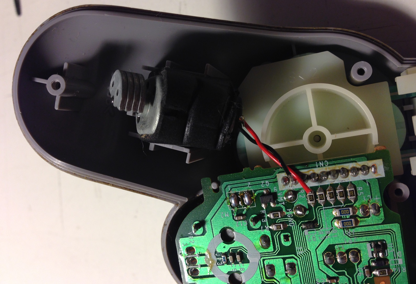
Dismounting the controller
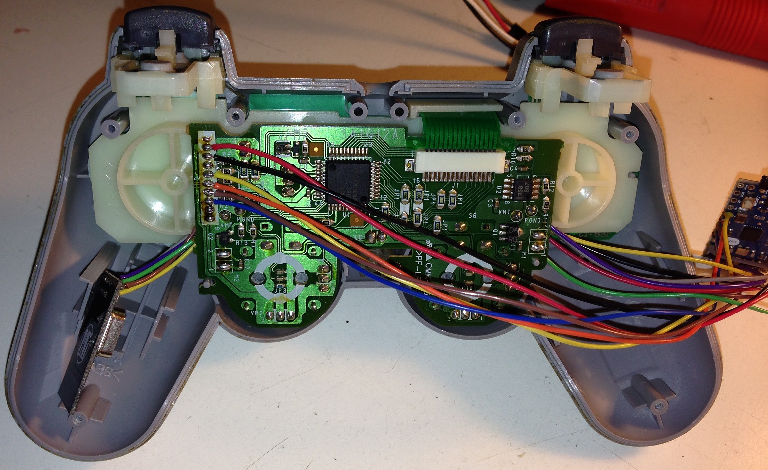
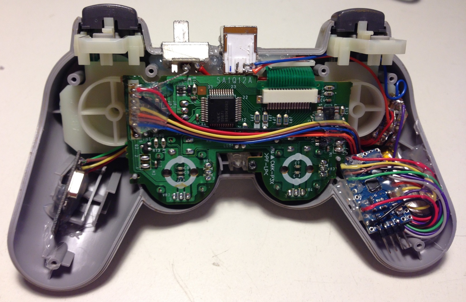
After removing all screws, the bottom part is detachable with ease. Inside are visible the controller’s board and two vibration motor’s. The board is connected with controller’s buttons via a flat cable (the green one with a white connector in the image below) and attached to the controller’s body with a single screw.
Remove both motors (we need some space) cutting each black and red wire and also detach the board unlocking the green flat cable and removing the screw.


Soldering communication and power wires
Desolder the main connector CN1 (the termination of controller’s cable on the circuit) and clean each hole. We need to solder some wires to these holes in order to permit communication between the controller’s board and the Arduino MINI board. Only 6 wires out of 9 must be soldered, following the pinout in the next figure:
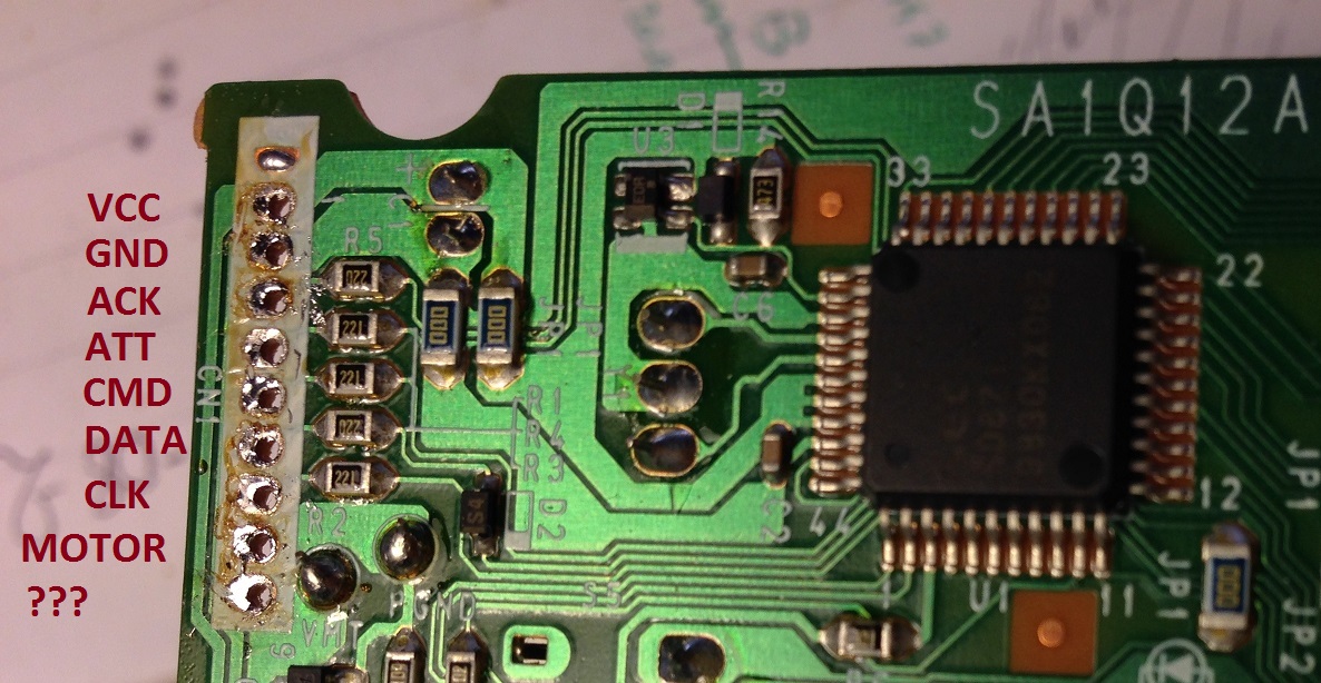
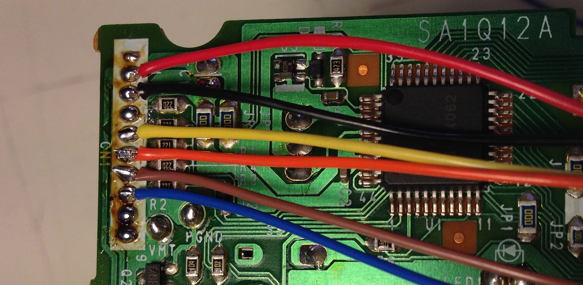
I’ve used colored wires to make everything more clear, be careful soldering wires to the board and watch out for shortcircuits.
- VCC – red wire
- GND – black wire
- ATT – yellow wire
- CMD – orange wire
- DATA – brown wire
- CLK – blue wire
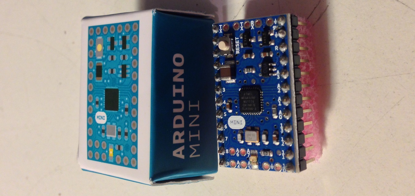
Testing the Arduino MINI board
It’s time to set aside the Playstation controller and take the Arduino MINI board. This board is one of the smallest and cheapest board produced by Arduino and has no USB to serial adapter neither a debugging LED. To power, program and debug the board an exernal USB-to-Serial adapter is needed but also another Arduino board (of course one with USB-to-Serial adapter) should go well. These are the board specifications:
| Microcontroller | ATmega328 |
| Operating Voltage | 5V |
| Input Voltage | 7-9 V |
| Digital I/O Pins | 14 (of which 6 provide PWM output) |
| Analog Input Pins | 8 (of which 4 are broken out onto pins) |
| DC Current per I/O Pin | 40 mA |
| Flash Memory | 32 KB (of which 2 KB used by bootloader) |
| SRAM | 2 KB |
| EEPROM | 1 KB |
| Clock Speed | 16 MHz |
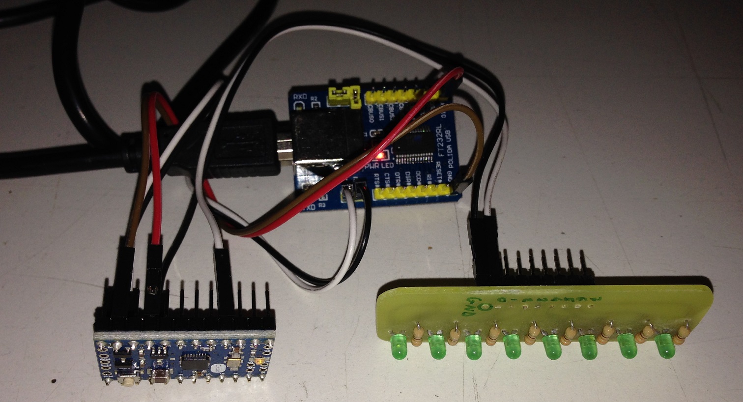
I have attached my board to an FT232RL board and a simple 8 LED array to do some testing and be sure that everything works as expected.
Next step is remove two headers at the bottom of Arduino MINI board and solder a 4 pin 90° angled header, making easily accessible these signals to program it:
- GND
- VCC
- RX
- TX
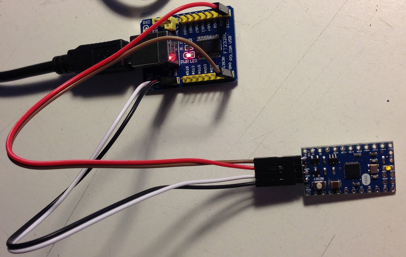
New connection to the USB-to-Serial converter is now more clean as it only needs 4 wires.
Connecting nRF24L01, Arduino MINI and Playstation controller board together
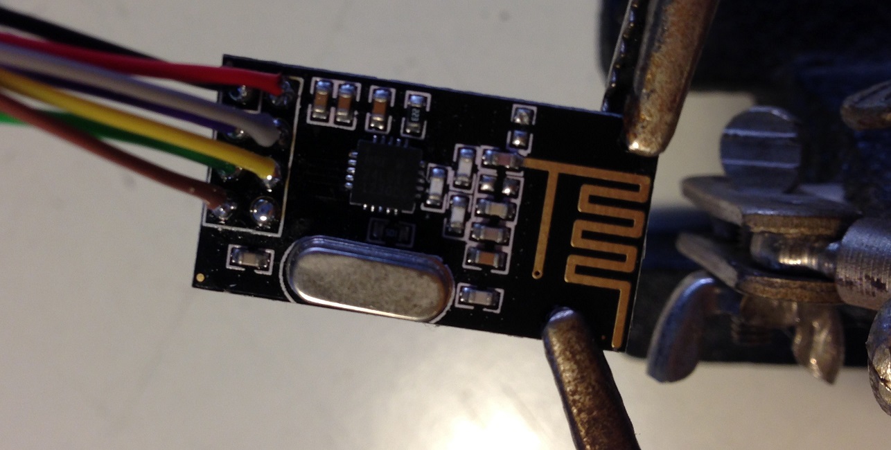
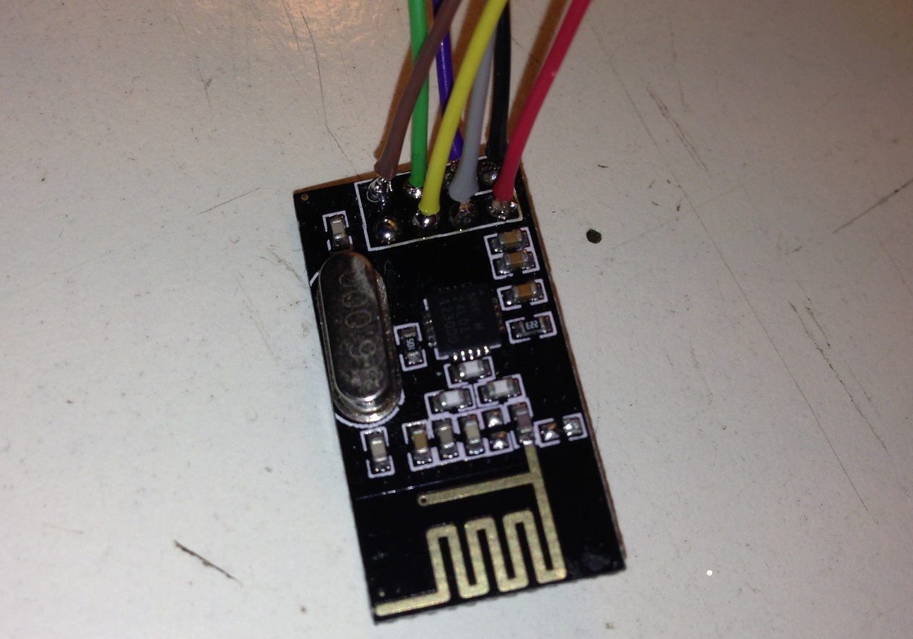
All modules need to be connected together, so we take the nRF24L01+ board removing the header. These are photos of nRF24L01+ module and the Arduino MINI board without headers.


The nRF24L01+ board pinout is listed below and consists in 6 different signal and 2 supply lines.
!!! nRF24L01 VCC can be at most 3.6V so DO NOT CONNECT to 5V provided by the USB bus or any higher voltage !!!
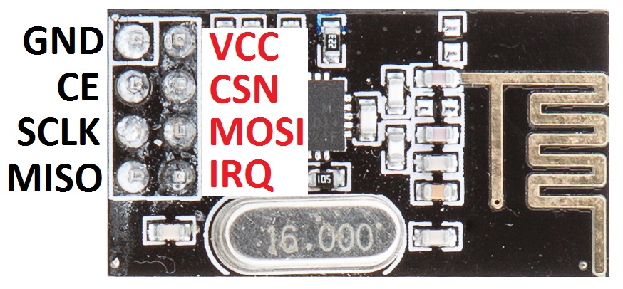
We need to connect a wire to 7 of these 8 PINs. The IRQ one is not needed in our application. Please be careful soldering wires to the board and watch out for shortcircuits. I have used colored wires again to simplify the connection.
- GND – red wire
- VCC – black wire
- CE – blue wire
- CSN – grey wire
- SCLK – green wire
- MOSI – yellow wire
- MISO – brown wire
- IRQ – no wire
Now that single modules have wires soldered, we are ready to connect them to the Arduino MINI board. Often we are free to choose to which Arduino’s GPIO connect each signal but the nRF24L01+ has an SPI interface and we want to use the hardware circuitry inside the Atmega328 chip to communicate with it.
I hope this table shows well how I have connected everything, following it you are free to just upload the Arduino sketch at the bottom of the post and see how it works with no need to modify anything.
| Playstation controller – ATT | Arduino PIN 2 |
| Playstation controller – CMD | Arduino PIN 3 |
| Playstation controller – DATA | Arduino PIN 4 |
| Playstation controller – CLK | Arduino PIN 5 |
| nRF24L01 – CSN | Arduino PIN 7 |
| nRF24L01 – CE | Arduino PIN 8 |
| nRF24L01 – MISO | Arduino PIN 12 |
| nRF24L01 – MOSI | Arduino PIN 11 |
| nRF24L01 – CLOCK | Arduino PIN 13 |
| Playstation controller – GND | Arduino PIN GND |
| Playstation controller – VCC | Arduino PIN VCC |
| nRF24L01 – GND | Arduino PIN GND |
| nRF24L01 – VCC | Arduino PIN VCC |
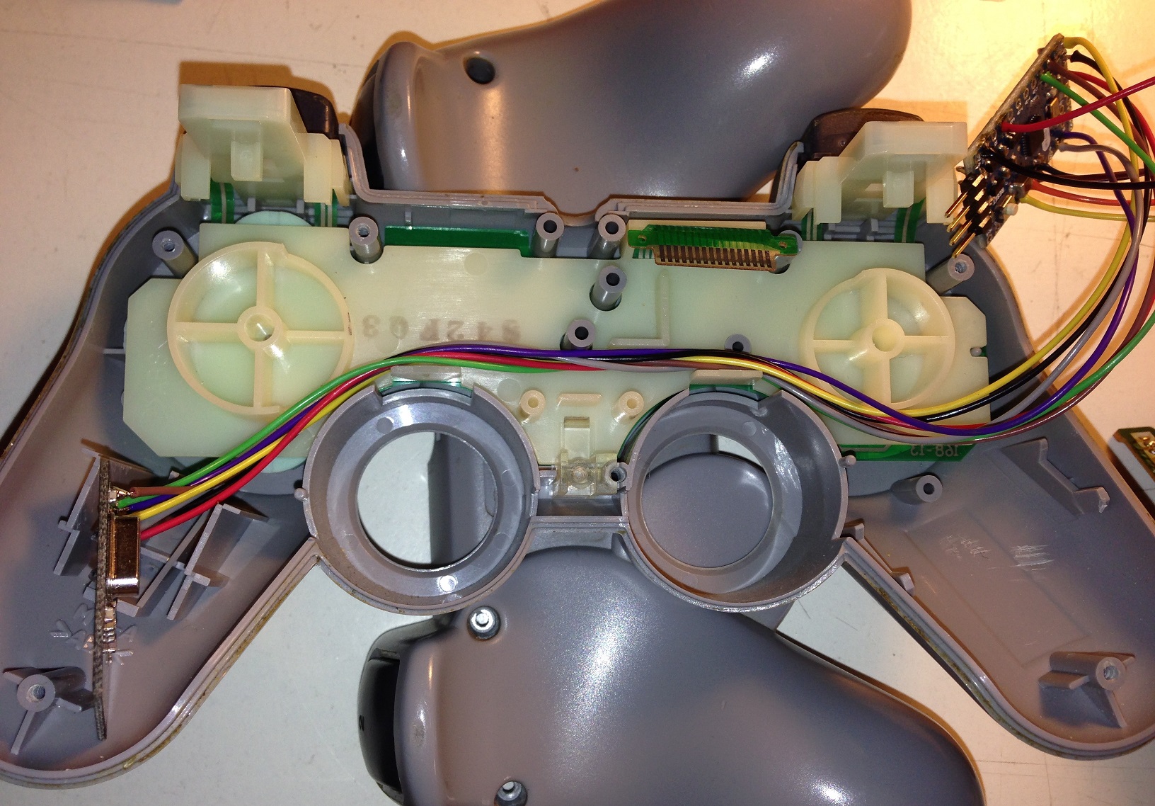
This is how my setup looks like.

And this is the view of Arduino MINI board with soldered cables.

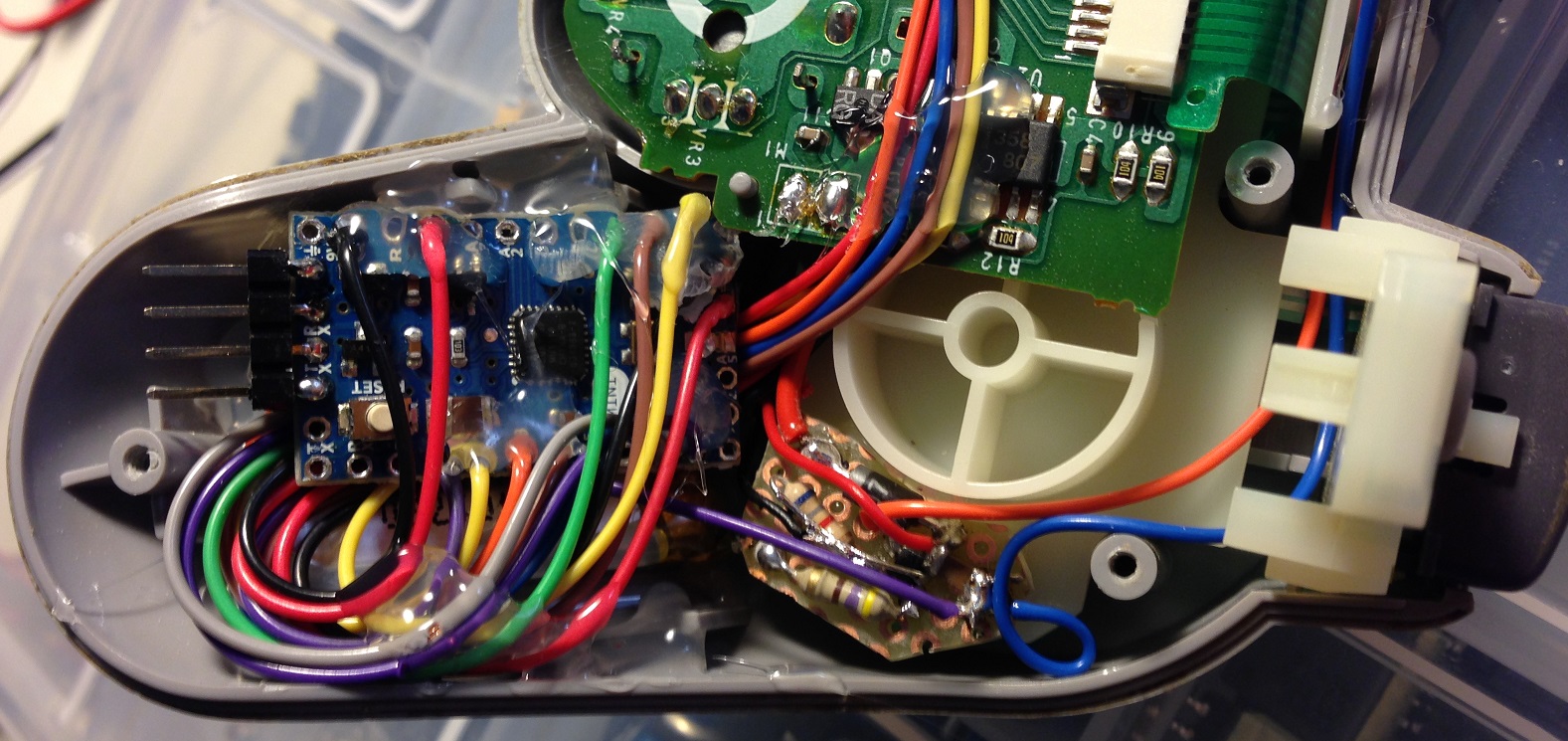
We are ready to partially reassemble the Playstation’s controller. The nRF24L01+ module should be placed in the left motor side, removing excess plastic to make some space for it. Use a cutter or a pair of scissors for this.
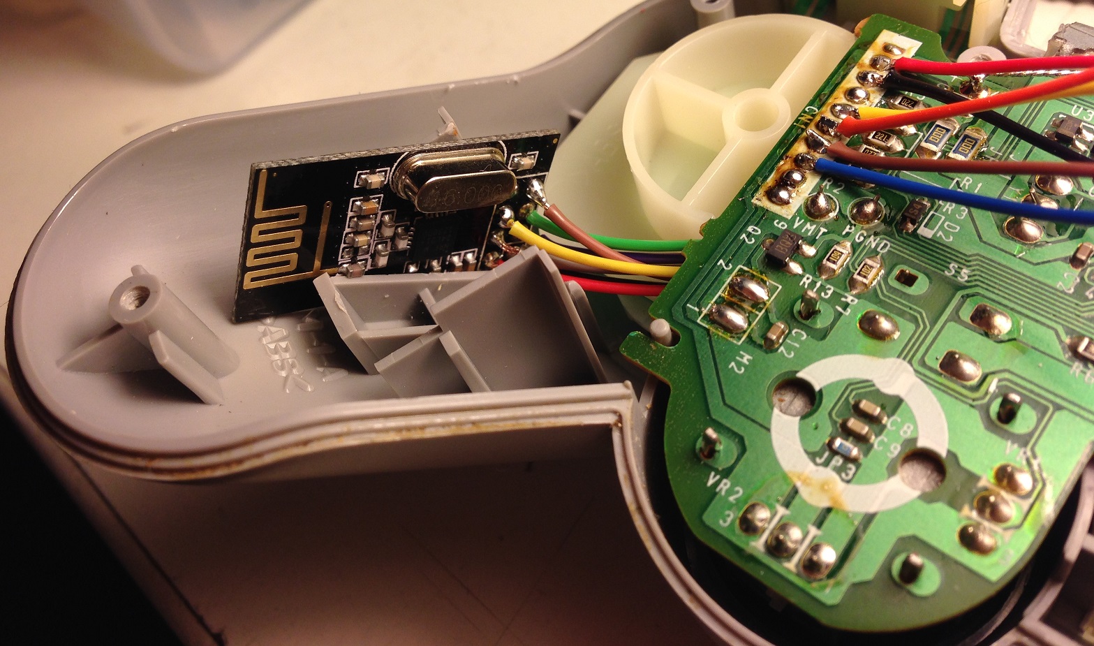
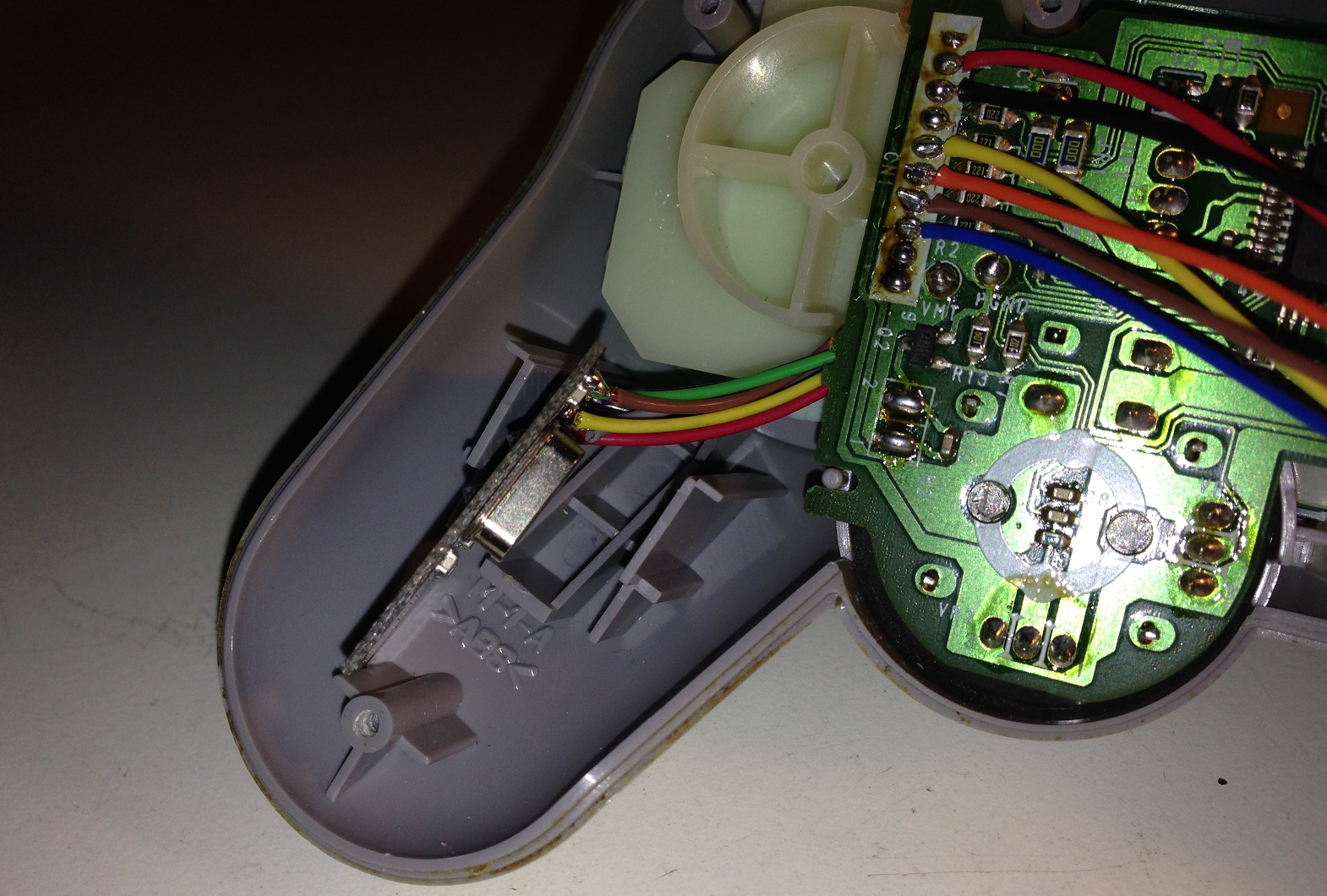
Cables from nRF24L01+ module to Arduino MINI board should pass under the Playstation controller‘s board, between the white plastic body as shown in figure.
Now, attach the Playstation controller‘s board to the controller’s body with the only screw and insert the green flat cable in the upper connector, beign careful to not ruin this part.
LiPo battery and USB battery charger
A small LiPo battery is enough to power the controller for a lot of time, nRF24L01+ module uses no more than 15mA, the Arduino MINI board with the controller’s circuit together about the same. Consider an exagerate 50mA usage, with this value a 150mA LiPo will last more than 3 hour!
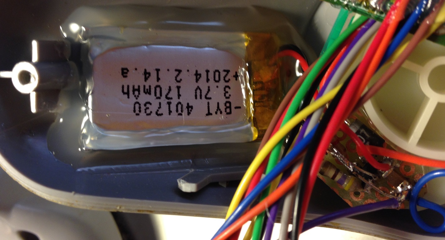
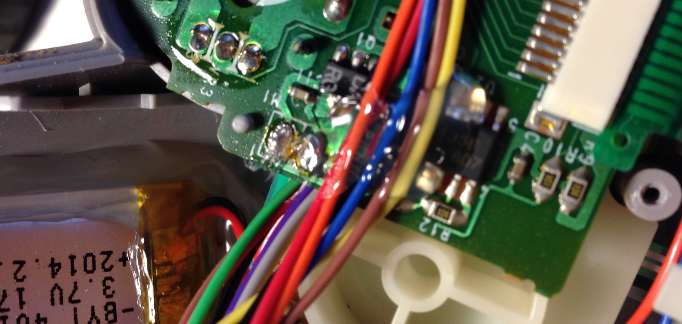
I have dismounted a Bluetooth A2DP module for another project and inside there was a little but perfect suited 170mA 3.7V LiPo.

Install the battery of your choice in the controller’s right side with long enough cables and fix it with hot glue.
BE CAREFUL!!! Hot glue is really hot and LiPo batteries can explode if overheated! So just add few hot glue each time, until it is fixed.
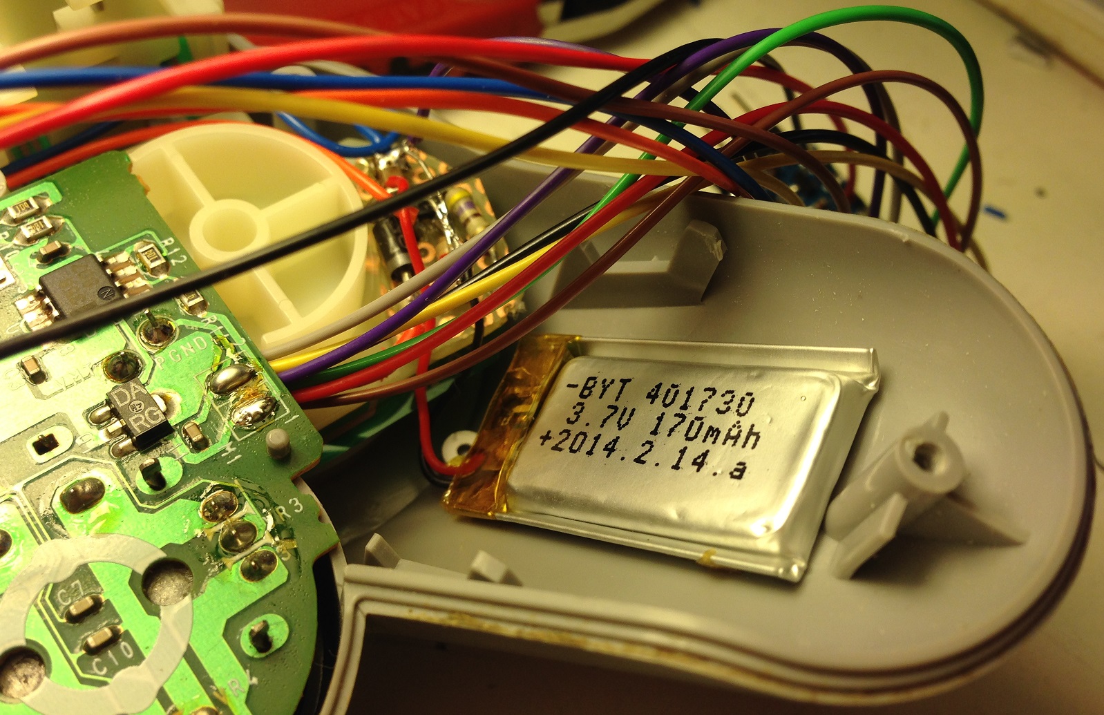
The little circuit realized on breadboard in bottom left part of last image is the USB charger. It is based on Microchip MCP73831 and few other components. I followed the typical application schematic on MCP73831‘s datasheet first page.
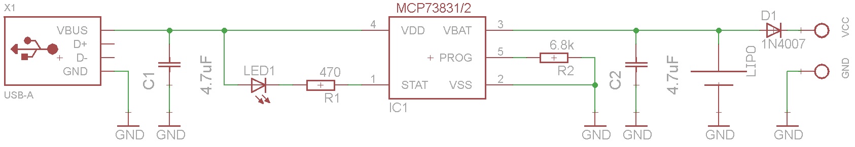
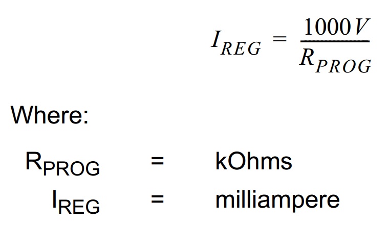
There are three main differences from the schematic on datasheet, the value of Rprog, an added diode D1 and I have not used the STAT LED. The R2 value determines the charging current and some other parameters, but the charging current is the only that really matters here. I changed it to correctly charge the battery, without generate too much heat, following this formula.
The diode instead is connected for a simple reason: LiPo batteries have a voltage that can reach 4.2V and the nRF24L01+ module instead can be supplied with at most 3.6V. A voltage regulator is surely the better choice but we have small space and we want to make things as much simple as possible.
Diodes like 1N4007 introduce a voltage drop when traversed by a current. In this circuit, with at least 15mA of flowing current, the voltage drop is enough to never let the output voltage be more than 3.6V, so our nRF24L01+ can work safely.
Realize this circuit and solder also the LiPo cables (be careful checking correct polarity and not shortcircuit), two GND wires, one VUSB wire and one VCC wire.
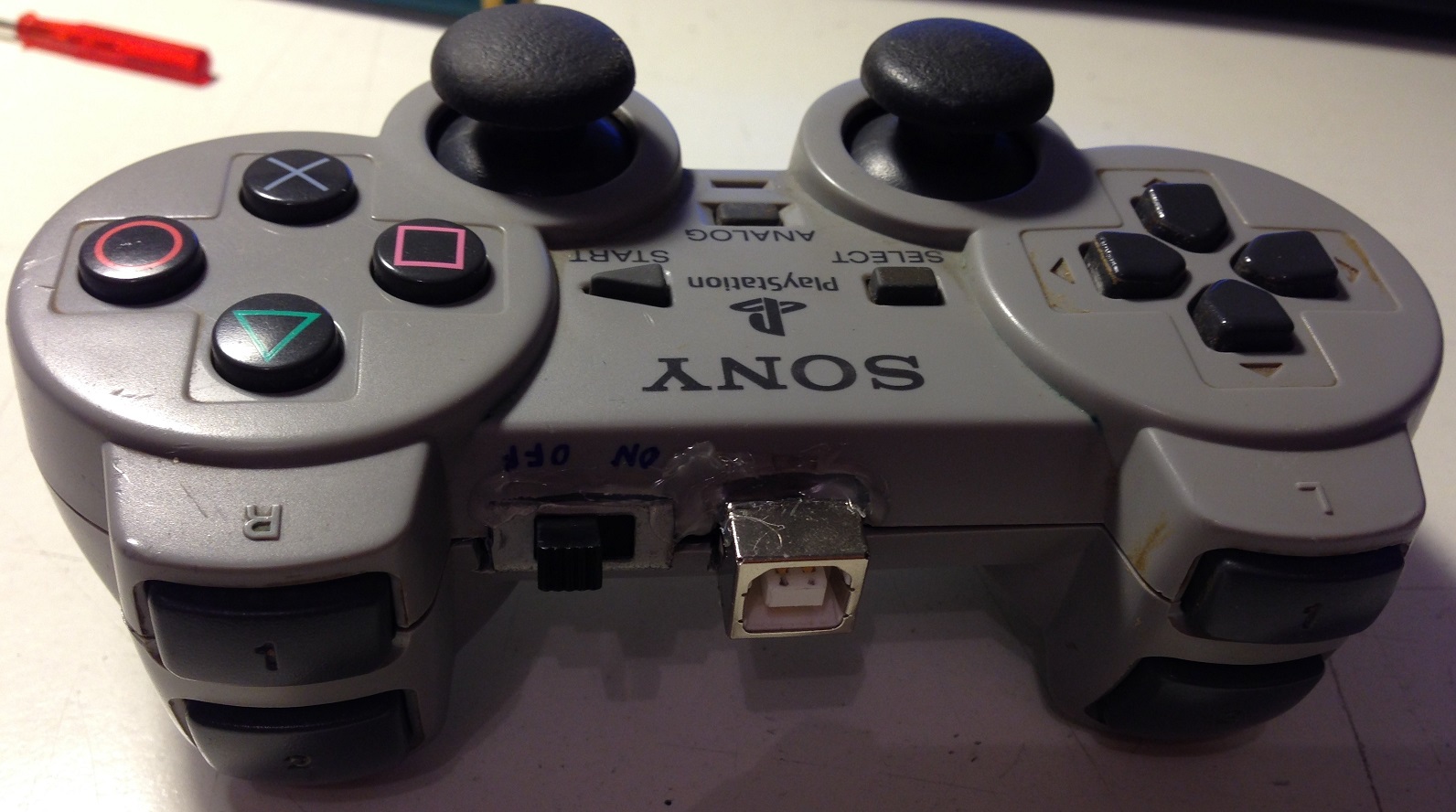
Power switch and USB connector
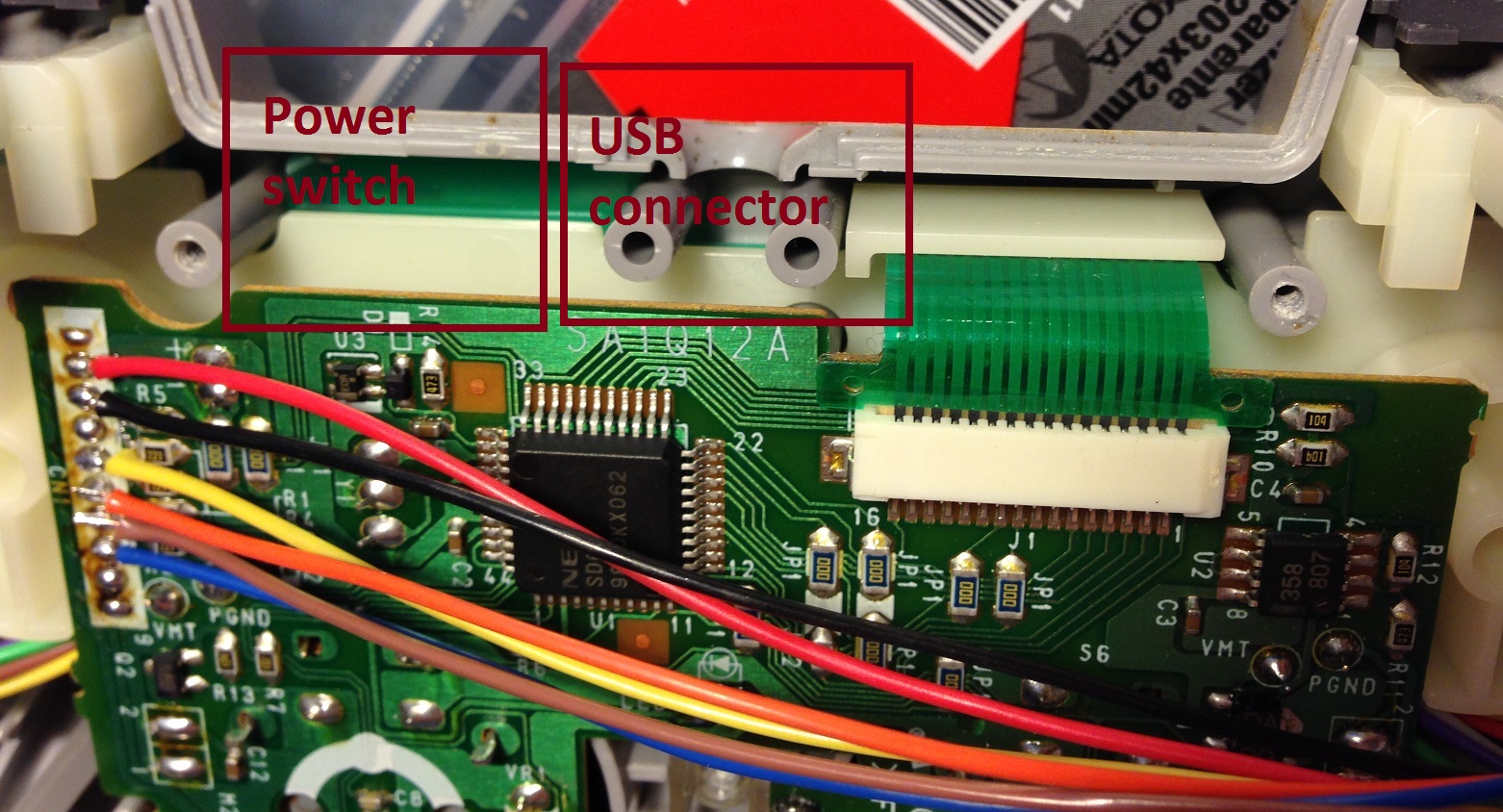
Use a tool of your choice from cutter, saw or scissor to make some space for an USB connect and a power switch in the upper side of the Playstation controller’s body. Then fix those elements with some hot glue. Take the LiPo charger circuit and solder the VUSB wire and one GND wire to the USB connector (check the correct polarity and if needed check your connector’s pinout on internet). Solder the LiPo charger’s VCC wire to one PIN of your power switch, another wire must be soldered on this switch to provide the main VCC to all electronics (just attach it to one of nRF24L01+, Arduino MINI or Playstation controller VCC PIN). I attached an image that shows how I have done it.

If needed, as in my case, remove some plastics also from the other part of the Playstation controller‘s body to make room for power switch and USB connector.
Fix cables and Arduino MINI board
We have quite done, just need to fix free cables and Arduino MINI board over the LiPo battery in the right side. Position the Arduino MINI baord in a way such that RX, TX, VCC and GND PINs are easily (more or less) accessible to program it. I used again hot glue and a lot of patience (my wires are fragile).

This is instead how it whole looks.
Congratulations, we have just finished the hardware part and we are ready to code!
Arduino code
I used the Arduino Mirf library to interface the nRF24L01+ module and I have modified the Arduino PSX Library to support also the analog sticks reading. This library is downloadable from HERE and feel free to test and modify it (let me know if you liked it).
This is the code of Arduino sketch.
You can also download the whole code from HERE. As you can see, the nRF24L01+ transmits about 8 byte of data every 50ms, far less than its full capacity of 2Mbps. After the initial setup in which we initialize the Arduino’s serial, nRF24L01+ and the Playstation’s controller, we start looping this sequence:
- Read the controller’s state
- If it is valid, create an nRF24L01+ compatible packet
- Send the packet and wait for sending complete
- Wait 50 ms
This controller sends packet to the defined tx_address, but you can change it. Also the packet structure can be modified, is clearly shown in the code statement how it is composed.
After you have checked that everything works, it’s time to close the controller’s body.
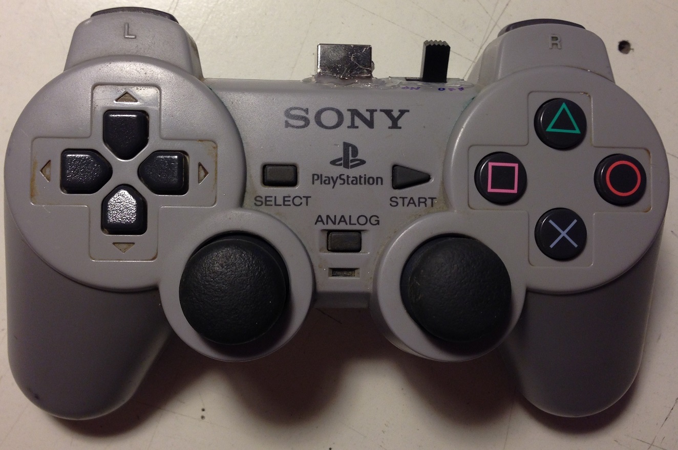
I know that this controller is really dirty but I’ll clean it, I swear!
Conclusions
This Playstation controller hack shows how to reuse an old device in a new way, it is really versatile and is a perfect companion to every project with the need of wireless control. Also devices non Arduino-based can be controlled, since it communicates over nRF24L01+ protocol. I have used this one to control a rover robot (on which I will write soon) and an RGB power LED.
Arquitecto especialista en gestion de proyectos si necesitas desarrollar algun proyecto en Bogota contactame en el 3006825874 o visita mi pagina en www.arquitectobogota.tk
0 comentarios:
Publicar un comentario