
Memorias mmc sd microsd

Wiki space sd ojpg
http://antikhyteradomotica.wikispaces.com/memorias+mmc+sd
Manual sd ( Informacion tecnica )MANEJO DE UNA MEMORIA SD/MMC CON UN PIC16F87x.
http://www.ladelec.com/practicas/colaboradores/alfredo-rossini/754-pic-18f4550-con-tarjeta-sd-y-archivos-de-texto

3) Es muy recomendable, que primero lean el trabajo: 88 - PIC 16F877 y 18F4550 usados para escribir y leer memoria SD Kingston de 2 GB y bajando el archivo ZIP:
3) Es muy recomendable, que primero lean el trabajo: 88 - PIC 16F877 y 18F4550 usados para escribir y leer memoria SD Kingston de 2 GB y bajando el archivo ZIP:

The SD card can be talked to with three different transfer modes: 1-bit SD mode, 4-bit SD mode and SPI mode. According to Wikipedia, all cards must support all three modes except for micro SD where the SPI mode is optional. I will nonetheless try to read my micro SD with the SPI mode.
Your microSD pin descriptions are wrong.
microSD Memory Card – Pins Definition
SD Mode
PIN NO NAME TYPE DESCRIPTION
1 DAT2 I/O/PP DATA Line [Bit 2]
2 CD / DAT3 I/O/PP Card Detect / DATA Line [Bit 3]
3 CMD PP Command / Response
4 VDD S Supply voltage
5 CLK I Clock
6 VSS S Supply voltage ground
7 DAT0 I/O/PP DATA Line [Bit 0]
8 DAT1 I/O/PP DATA Line [Bit 1]
1 DAT2 I/O/PP DATA Line [Bit 2]
2 CD / DAT3 I/O/PP Card Detect / DATA Line [Bit 3]
3 CMD PP Command / Response
4 VDD S Supply voltage
5 CLK I Clock
6 VSS S Supply voltage ground
7 DAT0 I/O/PP DATA Line [Bit 0]
8 DAT1 I/O/PP DATA Line [Bit 1]
SPI Mode
PIN NO NAME TYPE DESCRIPTION
1 RSV — Reserved (*)
2 CS I CHIP Select(Negative true)
3 DI I DATA IN
4 VDD S Supply voltage
5 SCLK I Clock
6 VSS S Supply voltage ground
7 DO O/PP DATA OUT
8 RSV — Reserved (*)
PIN NO NAME TYPE DESCRIPTION
1 RSV — Reserved (*)
2 CS I CHIP Select(Negative true)
3 DI I DATA IN
4 VDD S Supply voltage
5 SCLK I Clock
6 VSS S Supply voltage ground
7 DO O/PP DATA OUT
8 RSV — Reserved (*)
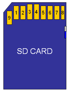
The SD card pinout is correct, and the uSD to SD converter will convert correctly, but from your graphics it would appear that uS D(1) is the same as SD(1) which it is not. The correct translator values is the following: (SD Bus)
(I destroyed a translator/converter to verify)
(I destroyed a translator/converter to verify)
SD, uSD, Description
9, 1, DAT2
1, 2, DAT3/CD
2, 3, CMD
4, 4, Vdd
5, 5, CLK
3&6, 6, Vss
7, 7, DAT0
8, 8, DAT1
9, 1, DAT2
1, 2, DAT3/CD
2, 3, CMD
4, 4, Vdd
5, 5, CLK
3&6, 6, Vss
7, 7, DAT0
8, 8, DAT1
Pinouts
Note: Diagrams somewhat to scale, not exact. Illustrative purposes only. Pin numbering is arbitrary. May not be consistent across all datasheets.Key: S: Power Supply; I: Input; O: Output; PP: Push-Pull
 |
| |||||||||||||||||||||||||||||||||||||||||||||||||||||||||||||||||||||||||||||||||||
 |
| |||||||||||||||||||||||||||||||||||||||||||||||||||||||||||||||||||||||||||||||||||
The information and layout of the following table was lifted from the Wikipedia page on the MultiMediaCard card standard:
| Type | MMC | SD | microSD |
|---|---|---|---|
| SPI Mode | Optional | Yes | Optional |
| 1 bit mode | Yes | Yes | Yes |
| 4 bit mode | No | Optional | Optional |
| Xfer clock | 0–20 MHz | 0–25 MHz - 0–50 MHz | 0–25 MHz? |
| Max Transfer | 20 Mbit/s | 100 Mbit/s - 200 Mbit/s | 100 Mbit/s |
| Max SPI Transfer | 20 Mbit/s | 25 Mbit/s | 25 Mbit/s |
| DRM Aval. | No | Yes | Yes |
The SD card
Let's have a look at the requirements to access an SD card via the simplest available protocol: SPI (Serial Peripheral Interface).
| SD Pin | SD function(SPI Mode) | Direction | The SD Card pin assignment |
|---|---|---|---|
| 1 | Chip Select (CS) * | IN |  |
| 2 | Data In (DI) | IN | |
| 3 | Ground | - | |
| 4 | Vcc (3.3v) | - | |
| 5 | Clock (CLK) | IN | |
| 6 | Ground | - | |
| 7 | Data Out (DO) | OUT | |
| 8 | Reserved | - | |
| 9 | Reserved | - | |
| (*) A low level on "Chip Select" selects the chip | |||
From this we can see what is needed:
- Ground
- Power, 3.3 volt
- 3 outputs (that are going to control the 3 inputs of the SD card)
- 1 input (that is going to read the data from the SD card output)
In fact we do not actually need to actively select the SD card via the Chip Select line. We can just always select it by grounding the signal. So in that case we only need 2 outputs. Now let's get to it and open our router to find what we need.


Use a 5.25 inch floppy disk cable connector. The pitch of this cable is the same as what is used with SD cards. This is quite a bulky solution, but it works ok. I'm not sure if you will be able to close your router when choosing this solution.
Can I use SDFS with MicroSD cards that have 8 pads? From searching in google, I found that these MicroSD cards can operate in two modes, SPI and SD modes. Please take a look at the attached pics.


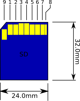
Secure Digital is what SD means, it is a flash based removable memory card. The card format may also be used other device functions in addition to data storage.

The SD card size dimensions are: 24mm wide x 32mm long. The standard width is 2.1mm, while the ThinSD Memory Card has a width 1.4mm.
| Pin | Pin Name | SD Signal Function SD Mode | SPI Signal Function SPI Mode |
| 1 | DAT3/CS | Data Line 3 | Chip Select/Slave Select [SS] |
| 2 | CMD/DI | Command Line | Master Out/Slave In [MOSI] |
| 3 | VSS1 | Ground | Ground |
| 4 | Vdd | Voltage Supply [2.7v or 3.6v] | Voltage Supply [2.7v or 3.6v] |
| 5 | Clock | Clock | Clock [SCK] |
| 6 | Vss2 | Ground | Ground |
| 7 | DAT0/D0 | Data Line 0 | Master In Slave Out [MISO] |
| 8 | DAT1/IRQ | Data Line 1 | Unused or IRQ |
| 9 | DAT2/NC | Data Line 2 | Unused |
MiniSD Card is a type of Removable NAND flash memory card format.
miniSD cards have memory capacities ranging from 256MB to 4GB. However, some of the capacity may be used for formatting and other functions, and not available for data storage. A miniSD card will fit in an SD card slot with a miniSD Adapter, miniSD Adaptes makes miniSD memory cards compatible with all SD-based devices.
There are 3 speed grades: Class 2, 2MB/s, Class 4, 4MB/s and class 6 card, 6MB/s.

The MiniSD Card measures 20mm x 21.5mm and 1.4mm thick.
| Pin # | Pin Name | SD Signal Function SD Mode | SPI Signal Function SPI Mode |
| 1 | CD/DAT3 | Chip Detect/Data Line 3 | Chip Select |
| 2 | CMD | Command Line | Data In [DI] |
| 3 | VSS1 | Ground | Ground |
| 4 | Vdd | Voltage Supply [2.7v or 3.6v] | Voltage Supply [2.7v or 3.6v] |
| 5 | Clock | Clock | Clock [SCK] |
| 6 | Vss2 | Ground | Ground |
| 7 | DAT0 | Data Line 0 | Data Out [DO] |
| 8 | DAT1 | Data Line 1 | Unused |
| 9 | DAT2 | Data Line 2 | Unused |
| 10 | NC | For future use | For future use |
| 11 | NC | For future use | For future use |
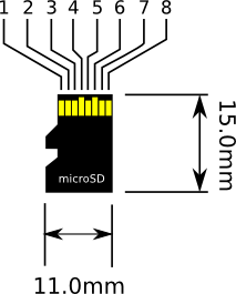
microSD Card is also a type of Removable NAND-type small flash memory card format, and has a dimensions of 11mm x 15mm and 1mm thick. MicroSD is short hand for Micro-Secure Digital [Transflash].

| Pin # | Pin Name | Signal Function |
| 1 | DAT2 | Data Bit 2 |
| 2 | CD/DAT3 | Card Detect / Data Bit 3 |
| 3 | CMD | Command Line |
| 4 | Vdd | Supply Voltage 2.7v / 3.6v |
| 5 | CLK | Clock |
| 6 | Vss | Ground |
| 7 | DAT0 | Data Bit 0 |
| 8 | DAT1 | Data Bit 1 |
| Pin # | Pin Name | Signal Function |
| 1 | NC | No Connect |
| 2 | /CS | Chip Select |
| 3 | DI | Master Out/Slave In (MOSI) |
| 4 | Vdd | Supply Voltage 2.7v / 3.6v |
| 5 | CLK | Clock |
| 6 | Vss | Ground |
| 7 | DO | Master In/Slave Out (MISO) |
| 8 | RSV | Reserved |

LECTO-GRABADOR de tarjetas MMC , SD, MicroSD con pic 16F877A
 ç
ç


Comenzando con memorias SD/MMC. Librería a nivel hardware.
Comenzando con memorias SD/MMC. Librería a nivel hardware.
Referencia
Reading an SD card with an ATMEGA168
Secure Digital (SD) Card Spec and Info
Deremate
Librerias
Petit fat
Lector de jpg con petit fat http://elm-chan.org/fsw/tjpgd/00index.html
PIC24 drum machine prototypehttp://catmacey.wordpress.com/2012/07/04/pic24-drum-machine-prototype/
Fat on pic 18f4620 http://www.electro-tech-online.com/microcontrollers/99795-sd-fat-pic.html
Usb y sd al tiempo con pic 24 http://desultoryquest.com/blog/fatfs-with-mal-usb/
Arquitecto especialista en gestion de proyectos si necesitas desarrollar algun proyecto en Bogota contactame en el 3006825874 o visita mi pagina en www.arquitectobogota.tk
0 comentarios:
Publicar un comentario