
Palm Multi-Connector

Close view of Palm Multi-Connector. Data cable connector features a hotsync button.
| |||
| Type | Communication, power supply, USB | ||
|---|---|---|---|
| Production history | |||
| Designer | Palm, Inc. | ||
| Superseded | Palm Universal Connector | ||
| General specifications | |||
| Pins | 18 | ||
The Palm Multi-Connector (also Athena Connector) is a power, audio and data interface connector designed by Palm, Inc.
Use[edit]
The connector is used by: LifeDrive, Tungsten E2, Tungsten T5, Treo 650, Treo 680, Treo 700p, Treo 750, Treo 755p, Palm TX, Palm Centro.
Changes[edit]
Palm, Inc. has changed the connectors it uses over time:
- some machines connect via Palm Universal Connector (Older Standard for Palm Handhelds)
- some machines use a standard Mini USB (Some Low-Budget Handhelds)
- some machines use a Multi-Connector (Newer standard for palmOne and Palm Handhelds)
- some early models used model-specific connectors.
The Connector can be used to charge the device, transfer data to a computer, HotSync, and play audio. It is the new standard to replace the previous Palm Universal Connector, which performed similar functions but did not have an audio output capability.
This port has also been used to connect to an external microphone or to GPS units
Specification[edit]
The connector is divided in two sections: the longer one has thirteen pins numbered from right to left (5 to 17); the shorter one has three pins, on the left (3), top (2) and right (1). The cable shield connectors (4,18) are located on each side of the thirteen pins.
| Pin # on device/Multiconnector | Pin # on charger/adapter connector | Pin# on data/cable connector | Name | Direction with respect to the device | Default state with no attachment | Function |
|---|---|---|---|---|---|---|
| 1 | 1 | VDOCK | Power | CHRG_IN | DC charging voltage, 5 V | |
| 2 | 2 | ADAPTER_ID | Input | VCC, weak pull-up | Adapter identification | |
| 3 | 3 | VDOCK_RTN | Power | GND | DC charging return | |
| 4 | 1 | SHIELD | Shield | GND | Cable shield | |
| 5 | 2 | VBUS | Power | VBUS_IN | USB charging voltage, 5 V typical, 500 mA max | |
| 6 | 3 | USB_DP | Input/Output | Floating | USB Data + | |
| 7 | 4 | USB_DN | Input/Output | Floating | USB Data - | |
| 8 | 5 | DGND | Power | GND | Digital ground, and VBUS return | |
| 9 | 6 | Reserved | NA | NA | Do not connect | |
| 10 | 7 | TXD | Input/output | VCC, weak pull-up | Transmit data, 3.3 V logic level | |
| 11 | 8 | RXD | Input | VCC, weak pull-up | Receive data, 3.3 V logic level | |
| 12 | 9 | HOTSYNC | Input | VCC, weak pull-up | HotSync input, active low, pulled up on device | |
| 13 | 10 | POWER_OUT | Output | High impedance | Power output to external devices | |
| 14 | 11 | SPKR_L | Analog output | AC coupled | Speaker output left | |
| 15 | 12 | SPKR_R | Analog output | AC coupled | Speaker output right | |
| 16 | 13 | AGND | Power | GND | Analog ground | |
| 17 | 14 | MIC_IN | Analog input | DC coupled | Microphone input | |
| 18 | 15 | SHIELD | Shield | GND | Cable shield |
Pins 10 and 11 have TTL levels and cannot be directly connected to the RS-232 port.
Opinion[edit]
The Multi-Connector has received criticism from users who were familiar with previous connectors such as the Universal Connector. Users have been frustrated with the requirement to replace their Universal Connector cables, cradles, keyboards, sleds, and attachments as they have become incompatible. Another criticism is that the connector is fiddly, harder to remove and feels fragile.
All that is needed to charge the Treo is to connect +5 V to VDOCK and 0 V (negative) to VDOCK_RTN.
External links[edit]
- Palm Developer Guide, Palm OS Platform. Look at section 14 for Multi-connector pinout
- Palm Multi connector pinout
- Palm Developer Network
Palm Universal connector
| Pin | Signal | Description |
| 1 | GND | Signal- and charge ground (connected to pin 7) [ GPS Ground ] |
| 2 | USB_D+ | Positive USB data signal [U1 green wire] |
| 3 | USB_D- | Negative USB data signal [U2 white wire] |
| 4 | VBUS | VBUS signal [U3 small red wire] |
| 5 | HOTSYNC | HotSync IRQ - +3.3V for button push (via pin 9) |
| 6 | N/C | Not Connected |
| 7 | GND | Signal- and charge GND (connected to pin 1) [U4 small black wire] |
| 8 | ID |
Identification for peripherials, resistor [R202=Zero Ohm] to ground. Should be short: USB cradle, 7.5 KOhm: Serial cradle, 20 KOhm: Mfg. Test Cradle, 47 KOhm: USB peripheral, 100 KOhm: Serial peripheral, 220 KOhm: modem
If pin 8 is shorted to ground, it forces USB mode. If left open, it forces Serial mode.
|
| 9 | Vout | +3.2V supply output, 100mA max. |
| 10 | RxD | RS-232 RxD signal (input), [GPS TX ] [D1] |
| 11 | TxD | RS-232 TxD signal (output), [ GPS RX ] [D2] |
| 12 | DETECT | peripheral detect - tied to ground by peripherals [D3] |
| 13 | CTS | RS-232 CTS signal (input) [D4] |
| 14 | RTS | RS-232 RTS signal (output) [D5] |
| 15 | DTR | RS-232 DTR signal (output) [D6] |
| 16 | CHARGE | +5V charge supply input, 500-700mA |
Palm USB cable:
Palm Universal connector (Tungsten T1, T2, T3, etc) has RS232 signals at RS-232 compatible levels, no voltage level translator from TTL to RS232 is needed. You can connect signals from your Palm Universal connect directly to PC or other compatible serial device.
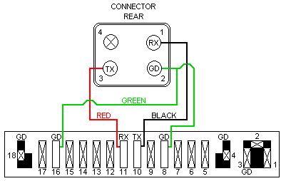
PC-Palm synchronization cable pinout:
Connector board === PALM UNI  ===  PC DB9 Female
D2 ------- 11 (TxD) ------- 2 (RxD)
D1 ------- 10 (RxD) ------- 3 (TxD)
SH1/2 ----  1 (GND) ------- 5 (GND)
D6 ------- 15 (DTR) ------- 6 (DSR)
D4 ------- 13 (CTS) ------- 7 (RTS)
D5 ------- 14 (RTS) ------- 8 (CTS)
ID1 ------  8 (DEV-ID)
E1/P1 ----  1 (PWR GND)
E2/P2 ---- 16 (PWR V+)
Pins 1, 7, and 12 should be shorted. Pin 8 should be tied to the other three via a tiny 7.5k resistor or left open. You may also want to bring out the two wires for the +5vdc charging connection, as well as tie pins 5 and 9 to a miniture push-button to initiate hot-sync.
Palm USB Cradle: USB to Serial Mod:
This mod allows you to use your Palm device on Windows 7 computers by connecting it via a USB to Serial adapter, yet keeping it connected to power so that it stays charged.
Windows Vista users should check to see if 32 or 64 bit drivers are available, and if so, can follow the instructions outlined below to adapt the cradle to serial use.
Note: you may need to download 32/64 bit drivers from Prolific's web site, depending on the model of the USB - Serial adapter used.
OIther versions of Windows, (XP and earlier), support both the serial and USB drivers originally supplied by Palm with their devices, so no mod is necessary.
The Mod:
The Palm USB cradle for these devices contains a small PCB to which the universal connector is attached. It can be found by carefully removing the four small screws under the four feet using a #10 Torx bit and separating the top and bottom halves of the cradle.
One side of this PCB has connections for the USB cable labeled U1 - U6, ID1, P1, P2, SH1.
The other side of the connector, has unused solder points to connect a Serial cable labeled D1 - D6, E1, E2, SH2.
ID1 is not an actual part of the USB cable and has no connection. The shorting connection for ID1 to enable USB mode is a small black device soldered just above the hot-sync switch. To adapt the cradle to use a serial connection exclusively, the small black shorting device just above the hot-sync switch should be removed.
E1/P1 and E2/P2 are charging power connections located at each end of the cradle's connector board, connected using heavier wire to the Palm charger's barrel connector. SH1/SH2 are provisions for each cable's shield ground connection. ID1 is the device identifier connection as noted above for Pin-8.
A USB cradle can be adapted to support both Serial and USB by adding an additional six conductor (with shield) cable, (and drilling a small hole in the back), wired to D1 - D6 on the connector board and a DB-9 (female) connector as noted on the diagram above.
A small switch or jumper block should be installed in the cradle's case and be soldered between ID1 (on the USB side of the PCB) and ground. After removing the tiny shorting device just above the HotSync switch, you can short the two pins (or throw the switch) to enable USB mode. Opening the connection enables Serial mode.
Arquitecto especialista en gestion de proyectos si necesitas desarrollar algun proyecto en Bogota contactame en el 3006825874 o visita mi pagina en www.arquitectobogota.tk
0 comentarios:
Publicar un comentario